Affiliate disclosure: This guide contains affiliate links. If you purchase through these links, SimTuts earns a small commission at no extra cost to you. We only recommend products we genuinely believe improve the flight sim experience.
The Garmin G1000 is the glass cockpit you will spend the most time staring at if you fly general aviation in MSFS 2024. It replaces the traditional round dials with two large screens and puts your engine data, navigation, weather, and flight planning into one integrated system. It is also the avionics suite that trips up more simmers than any other, because it looks intuitive until you try to load an approach and suddenly nothing works the way you expected.
This guide covers everything you need to operate the G1000 and its more advanced sibling, the G3000, in Microsoft Flight Simulator 2024. No fluff, no theory-only explanations. You will learn what each display section does, how to build a flight plan, how to use the autopilot properly, and how to avoid the mistakes that leave pilots circling the airport wondering why the CDI needle is not moving.
What Is the Garmin G1000?
The Garmin G1000 is an electronic flight instrument system (EFIS) that was introduced in 2004 and quickly became the most popular integrated glass cockpit in general aviation. It replaces six traditional round instruments, a separate GPS navigator, and standalone engine gauges with two large display units and a unified avionics architecture.
In MSFS 2024, the G1000 implementation is based on the Working Title NXi enhancement that was originally a free marketplace add-on. It is now integrated into the default avionics, meaning every G1000-equipped aircraft benefits from improved navigation, VNAV support, and more accurate approach guidance out of the box.
Which MSFS 2024 Aircraft Use the G1000?
These default aircraft in MSFS 2024 come equipped with the Garmin G1000:
- Cessna 172 Skyhawk (the most popular trainer)
- Cessna 208B Grand Caravan EX (single-engine turboprop)
- Cessna C408 SkyCourier (twin turboprop)
- Cessna C400 Corvalis TT (high-performance piston single)
- Diamond DA-40 NG (single-engine trainer)
- Diamond DA62 (twin-engine piston)
- Beechcraft Baron G58 (twin-engine piston)
- Cirrus SR22T NXi (high-performance piston single)
If you are learning the G1000 for the first time, the Cessna 172 Skyhawk is the best starting point. It is the simplest airframe, so you can focus entirely on the avionics without being overwhelmed by complex engine management.
Understanding the Displays: PFD and MFD
The G1000 has two screens. The left screen is the Primary Flight Display (PFD). The right screen is the Multi-Function Display (MFD). Each has its own set of softkeys along the bottom edge and dual concentric FMS knobs on the bezel.
The Primary Flight Display (PFD)
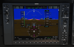
The PFD replaces your traditional six-pack of flight instruments. Everything you need to fly the aircraft is on this one screen, arranged in a familiar layout.
Center: Attitude Indicator. The large blue-and-brown display fills the middle of the PFD. Major pitch lines are marked every 10 degrees, with minor pitch marks at 2.5-degree intervals near the horizon (between 20 degrees nose-down and 20 degrees nose-up) and at 5-degree intervals beyond that (up to 25 degrees nose-down and 45 degrees nose-up). Roll markings appear at 10, 20, 30, 45, and 60 degrees on each side. A fixed yellow chevron at the center represents your aircraft's wings.
Left: Airspeed Tape. A vertical scrolling tape replaces the traditional airspeed indicator. Color bands show the operating ranges: the white arc is the flap operating range, green is normal, and yellow is caution. A magenta trend vector extends from your current speed to show where your airspeed will be in about six seconds, which is incredibly useful for monitoring acceleration and deceleration.
Right: Altimeter Tape. Another vertical scrolling tape with a digital readout of your current altitude. The barometric pressure setting (altimeter setting) is displayed below the tape. You set this using the BARO knob on the PFD bezel.
Far Right: Vertical Speed Indicator. A scale beside the altimeter tape showing your rate of climb or descent in feet per minute.
Bottom: Horizontal Situation Indicator (HSI). The compass rose at the bottom of the PFD is your primary navigation display. It shows your current heading, the heading bug (a cyan marker), the CDI needle (course deviation), bearing pointers if enabled, and the active navigation source. This is the single most important piece of the PFD for navigation, and it is where most confusion happens.
Bottom-Left Corner: Wind Data and OAT. The outside air temperature is displayed in degrees Celsius, and wind direction and speed information appear here when available.
Bottom-Right Corner: Transponder Code. Your selected squawk code is displayed in a box at the bottom right.
Softkeys (Bottom Row). The row of buttons along the bottom of the PFD gives you quick access to functions like the inset map, CDI source switching, bearing pointer selection, and display settings. The CDI softkey is one you will use constantly.
The PFD layout described above: airspeed left, attitude centre, altitude and vertical speed right with the barometric setting under the altitude tape, and the HSI below with its cyan heading bug and the GPS source label. CDI sits on the softkey row along the bottom. Our trainer does not draw the wind, OAT or transponder boxes. Rendered by our own G1000 trainer.
The Multi-Function Display (MFD)
The MFD is your information management screen. By default, it shows two things: engine instrumentation on the left, and a moving map on the right.
The MFD's default split: engine gauges down the left, the navigation map on the right. The page group tabs (MAP, WPT, AUX, FPL, NRST) run across the top.
Left Side: Engine Indication System (EIS). This section displays all critical engine parameters: RPM, manifold pressure, fuel flow, oil temperature, oil pressure, cylinder head temperature, exhaust gas temperature, fuel quantity, and electrical system data. The exact gauges depend on the aircraft type.
Right Side: Moving Map. The map shows your aircraft position, your flight plan route (the leg being flown drawn magenta, the rest white), airports, navaids, airspace boundaries, and optionally terrain, traffic, and weather overlays.
Page Groups. Using the FMS knobs, you can switch the MFD to other pages beyond the default map:
- Flight Plan page — shows all waypoints in your active route with distances and ETEs
- Procedures page — where you load departures, arrivals, and approaches
- Nearest page — lists the closest airports, VORs, NDBs, and intersections
- Traffic page — displays TAS/TIS traffic
- Terrain page — color-coded terrain awareness (red = at or above your altitude, yellow = within 1,000 ft below, green/black = more than 1,000 ft below)
The FMS Knobs: Your Primary Input Device
The dual concentric FMS knob on each display bezel is how you interact with the G1000. Understanding it is essential because almost every task flows through these knobs.
Outer Ring (Large Knob): Moves between page groups on the MFD, or moves the cursor between fields when entering data.
Inner Ring (Small Knob): Scrolls within a page group, or changes the value within a selected field (scrolling through letters, numbers, or list options).
Push (Press the knob in): Activates or deactivates the cursor, depending on context. On the PFD, pressing the FMS knob toggles the cursor on the inset map or enters certain configuration menus.
When entering a waypoint identifier, you turn the small FMS knob to scroll through letters and numbers, then turn the outer knob to move to the next character position, repeating until the full identifier is entered. Press ENT to confirm.
Building a Flight Plan
Flight plan entry on the G1000 is done entirely through the MFD.
Step-by-Step: Enter a Flight Plan
- Press the FPL button on the MFD bezel. This opens the active flight plan page.
- Press the FMS knob to activate the cursor. An empty waypoint field appears.
- Turn the small FMS knob to scroll through characters. Spell out your departure airport's ICAO identifier letter by letter (for example, K-J-F-K).
- Press ENT to confirm the airport. The G1000 will look it up in its database.
- The cursor moves to the next empty row. Repeat the process for each enroute waypoint — VORs, intersections, or GPS waypoints.
- Enter your destination airport as the final waypoint.
- Once all waypoints are entered, press the FMS knob to deactivate the cursor.
- Verify your route appears on the MFD map. The leg you are being guided along right now draws magenta; every leg beyond it draws white. One magenta leg with white legs ahead of it is exactly what a working flight plan looks like — white is not a warning. You do not need to activate anything: creating the plan in the active flight plan window activates its first leg automatically.
Using Direct-To
If you just need to navigate to a single waypoint without building a full flight plan — for instance, during a VFR flight or when ATC gives you a direct clearance — the Direct-To function is faster.
- Press the Direct-To button (marked with a D and an arrow, sometimes written as D→) on the bezel.
- Enter the waypoint identifier using the FMS knobs.
- Press ENT. The cursor moves to "ACTIVATE?"
- Press ENT again to activate. The G1000 immediately begins navigating you direct to that waypoint.
You can also use Direct-To with a waypoint already in your flight plan. Press D→, then turn the small FMS knob to the left to display a list of your flight plan waypoints. Select the one you want and press ENT twice.
Once the Direct-To is activated, the map draws a magenta course from the aircraft's present position straight towards the waypoint, here KTCY.
Both of these are gestures rather than facts, and knob sequences stick faster from doing them than from reading them. Our browser G1000 trainer runs both free, no sim and no download: Build a flight plan is the FPL sequence above, step for step, and Fly Direct-To a waypoint is the D→ one.
Get flight sim tips in your inbox
New guides, checklists, and tips. No spam. Unsubscribe any time.
Autopilot Integration: The GFC 700
The autopilot in most G1000-equipped aircraft is the Garmin GFC 700. Its controls are a row of buttons typically located on the panel above or near the PFD. Understanding each button and mode is critical, because selecting the wrong mode at the wrong time is one of the most common sources of confusion.
Autopilot Buttons and What They Do
AP (Autopilot): Engages the autopilot and flight director. When you press AP, the system defaults to ROL (Roll Hold) for lateral control and PIT (Pitch Hold) for vertical control. This means the autopilot holds roughly your current attitude. If you are in a small bank (under 6 degrees), it rolls wings level. In a moderate bank (between 6 and 22 degrees), it holds the current angle. In a steep bank (above 22 degrees), it rolls back to hold approximately 22 degrees.
FD (Flight Director): Turns on the flight director bars on the PFD without engaging the autopilot servos. The magenta command bars show you where to fly if you want to hand-fly with guidance. This is useful during approaches where you want visual steering cues without the autopilot controlling the aircraft.
HDG (Heading): Commands the autopilot to fly the heading set by the heading bug on the HSI. The heading bug is the cyan (light blue) marker on the compass rose. Rotate the HDG knob to move it. Push the HDG knob to sync the bug to your current heading. The autopilot commands a standard rate turn (3 degrees per second) to intercept and hold the selected heading, with the actual bank angle depending on your airspeed.
NAV (Navigation): Commands the autopilot to follow the active navigation source — either GPS or a VOR/localizer, depending on what the CDI is set to. For GPS navigation, the aircraft follows the magenta flight plan line. For VOR navigation, it tracks the selected VOR radial displayed in green.
APR (Approach): Arms approach coupling. This is similar to NAV mode but with tighter CDI sensitivity appropriate for approach operations. It also arms glideslope or glidepath capture for ILS and LPV approaches. When flying an ILS, pressing APR arms both the localizer (lateral) and glideslope (vertical) for automatic capture. You must press APR before intercepting the final approach course.
BC (Back Course): Reverses the localizer sensing for back-course localizer approaches. This is rarely used, but it exists for airports with back-course procedures.
VS (Vertical Speed): Commands the autopilot to hold a specific rate of climb or descent. After pressing VS, use the NOSE UP and NOSE DN buttons to set the desired rate in 100 FPM increments. The aircraft will pitch to maintain that rate. Be cautious using VS for climbs at higher altitudes, as the aircraft may not have enough power to maintain both the target VS and a safe airspeed.
FLC (Flight Level Change): Commands the autopilot to climb or descend at a constant airspeed. After pressing FLC, use NOSE UP and NOSE DN to set the target airspeed. The autopilot adjusts pitch to maintain that speed, with the rate of climb or descent varying based on available power. FLC is generally the preferred mode for climbs because it prevents inadvertent stalls — the autopilot will trade climb rate for safe airspeed.
ALT (Altitude Hold): Captures and holds the current altitude. Also used for altitude preselect capture: if you set a target altitude with the ALT knob and the aircraft reaches it while in VS or FLC mode, ALT mode engages automatically to level off.
VNV (Vertical Navigation): Provides VNAV path guidance for descents along published altitude constraints. This is functional in the NXi version integrated into MSFS 2024 and is particularly useful for RNAV arrivals and approaches with step-down fixes.
NOSE UP / NOSE DN: These are not modes themselves, but adjustment buttons. They change the target value for whatever vertical mode is active: vertical speed in VS mode, or target airspeed in FLC mode.
The ALT Knob
The altitude preselect knob has two rings. The outer ring adjusts altitude in thousands of feet. The inner ring adjusts in hundreds of feet. Always set your target altitude before engaging a vertical mode. When the aircraft reaches the preselected altitude during a VS or FLC climb or descent, the autopilot automatically levels off and switches to ALT hold.
Loading and Flying an Approach
This is where the G1000 trips up most simmers. The approach loading process has several steps, and missing any one of them can leave you with an approach that does not work as expected.
Step-by-Step: Load an Approach
- Press the PROC button on the MFD bezel. This opens the procedures page.
- Select "Select Approach" using the FMS knob and press ENT. If you have a flight plan with a destination airport, it defaults to that airport.
- Scroll through available approaches with the small FMS knob. You will see ILS, LOC, RNAV (GPS), VOR, and NDB approaches listed with their runway numbers.
- Select your approach and press ENT.
- The cursor moves to the Transition field. A transition is the routing from the enroute structure to the initial approach fix (IAF). Select a transition, or choose Vectors-to-Final (VTF) if you expect ATC to give you radar vectors to the final approach course.
- Press ENT after selecting the transition.
- You now see two options: LOAD and ACTIVATE.
Load vs. Activate: When to Use Each
LOAD inserts the approach waypoints into your flight plan but does not immediately begin sequencing to them. This is what you should choose initially — it sets everything up without disrupting your current navigation. You can continue flying your enroute portion while the approach is ready in the background.
ACTIVATE immediately makes the first approach waypoint the active waypoint and begins sequencing. Only use this when you are actually cleared for the approach and ready to fly it.
The professional technique is to Load first, Activate later. Load the approach while you are still 50 or 100 miles out. When ATC clears you for the approach, press PROC, select "Activate Approach," and the sequencing begins. If ATC gives you a direct to a specific approach waypoint, you can also use the Direct-To button to go direct to that fix.
CDI Source: The Most Common Mistake
Before flying any approach, check the CDI source annunciation at the top of the HSI on the PFD.
- GPS (magenta arrow) — used for RNAV (GPS) approaches, and for GPS overlay during the enroute portion of ILS and VOR approaches
- VOR1 or LOC1 (single green arrow) — used for VOR or ILS/LOC approaches using NAV1
- VOR2 or LOC2 (double green arrow) — uses NAV2
Press the CDI softkey on the PFD bottom row to toggle between these sources.
CDI on GPS: the course needle and the source label are magenta.
One press of CDI later: the source reads VOR1, because NAV1 is tuned to a VOR frequency, and the needle is a single green arrow. With a localizer frequency in NAV1 the same press shows LOC1.
For ILS approaches: The G1000 will automatically switch the CDI from GPS to LOC1 when you reach the approach segment, provided you loaded and activated the approach correctly. However, you should verify this happens. If you see the CDI still showing GPS when you should be tracking the localizer, press CDI to switch manually.
For VOR approaches: The G1000 does not automatically switch from GPS to the VOR. You must manually press CDI to switch to VOR1 and ensure the correct VOR frequency is tuned. This catches many pilots off guard.
For RNAV (GPS) approaches: The CDI stays on GPS throughout. Watch the approach annunciation on the PFD — it should show the approach type (LPV, LNAV/VNAV, LNAV+V, LP+V, or LNAV) depending on the approach and available WAAS signal.
The softkey press is the whole fix, and it is worth building the reflex somewhere a wrong source costs nothing. Change the navigation source (CDI) is free on our browser G1000 trainer and drills exactly this toggle; the Premium Set up an ILS approach scenario then runs the load-activate-verify sequence the auto-switch depends on.
Flying the Approach with the Autopilot
- Load and activate the approach as described above.
- Press APR on the autopilot to arm approach mode.
- For ILS: the autopilot will capture the localizer and then the glideslope automatically. You will see "LOC" and "GS" appear in the annunciator strip on the PFD when captured.
- For RNAV/GPS: the autopilot follows the GPS course and the VNV path (if active).
- Monitor the approach. Disconnect the autopilot at your decision altitude or minimums and hand-fly the landing.
The Garmin G3000: Touchscreen Avionics
The Garmin G3000 is the G1000's more capable sibling, introduced in 2009 and designed for turboprop and light jet aircraft. The biggest difference you will notice immediately is the touchscreen interface.
Which MSFS 2024 Aircraft Use the G3000?
The primary default aircraft with G3000 avionics in MSFS 2024 is:
- Daher TBM 930 — single-engine turboprop
The Cessna Citation Longitude, which some simmers assume uses the G3000, actually uses the Garmin G5000 — a related but different system designed for larger cabin-class jets.
Third-party add-ons like the FlightFX Cirrus Vision Jet SF50 also implement the G3000 in MSFS 2024, but these are marketplace purchases rather than default aircraft.
Key Differences from the G1000
Touchscreen Controllers (GTC). Instead of softkeys and the dual concentric FMS knobs as your primary input, the G3000 uses two GTC 570 touchscreen controllers mounted forward of the throttle quadrant. These are separate from the main PFD and MFD screens. You tap icons and menu items on the touchscreens to manage navigation, radio frequencies, autopilot settings, and system configuration.
The GTC 570 also has three physical controls at the bottom of the unit: a volume knob, a map joystick for panning the map, and a dual concentric knob for data entry. You can use either the touchscreen or the knobs — the current function of the knobs is always labeled on screen.
Larger Displays. The G3000 in the TBM 930 uses three landscape-oriented screens (two PFDs and one MFD), each measuring 12 inches diagonally (GDU 1200W) at 1280 x 800 resolution. Other G3000 installations (such as the Cessna Citation M2) use even larger 14.1-inch displays, but in MSFS 2024 the TBM 930 is the primary default G3000 aircraft.
Synthetic Vision. While the G1000 NXi in MSFS 2024 also supports a basic synthetic vision view, the G3000's SVT (Synthetic Vision Technology) is more detailed, rendering three-dimensional terrain on the PFD. You can enable or disable this on the GTC through PFD Home, then PFD Settings, then SVT Terrain Enable.
Flight Plan Entry. On the G3000, you enter flight plans through the GTC touchscreen rather than the FMS knobs. You tap the Flight Plan page, use the on-screen keyboard to type waypoint identifiers, and tap to confirm. The basic logic is the same as the G1000 — departure, waypoints, destination — but the interface is more visual and arguably faster for data entry.
Approach Loading. Approach loading follows the same conceptual flow (PROC, select approach, choose transition, load or activate), but everything is done through the touchscreen menus rather than the FMS knobs. The touch interface makes it easier to browse available approaches since you can see more information on screen at once.
What Stays the Same
Despite the different interface, the underlying navigation and autopilot concepts are identical between the G1000 and G3000. The CDI source logic, the Load vs. Activate approach workflow, the autopilot modes (HDG, NAV, APR, VS, FLC), and the flight plan structure all work the same way. If you learn the G1000 thoroughly, transitioning to the G3000 is straightforward — you just need to learn where things are on the touchscreen.
Common Mistakes and How to Fix Them
1. Wrong CDI Source
The problem: You loaded an approach but the autopilot is not tracking it, or the CDI needle is not responding. The most common cause is having the CDI set to the wrong source — GPS when you need LOC, or VOR when you need GPS.
The fix: Always glance at the CDI source annunciation on the HSI before engaging APR mode. Press the CDI softkey on the PFD to cycle through GPS, VOR1, and VOR2 until you have the correct source selected for your approach type.
2. Approach Loaded but Not Activated
The problem: You loaded the approach 50 miles out (correct), but you forgot to activate it when you were cleared. The approach waypoints are in the flight plan, but the autopilot continues to fly past them because the system is still navigating the enroute waypoints.
The fix: When ATC clears you for the approach, press PROC, then select "Activate Approach." Alternatively, use the Direct-To button to go direct to the specific approach fix ATC has assigned.
3. Activating the Approach Too Early
The problem: You press "Activate Approach" when you are still 80 miles from the airport. The G1000 immediately tries to navigate you to the initial approach fix, potentially turning you off your current course and confusing ATC.
The fix: Load first, activate later. Only activate when you are approaching the terminal area and have been cleared for the approach, or when ATC instructs you to proceed to an approach fix.
4. Vectors-to-Final Confusion
The problem: You selected Vectors-to-Final (VTF) when loading the approach because ATC said "expect vectors." Now the G1000 has set the Final Approach Fix (FAF) as the active waypoint and is trying to fly you direct to it, even though ATC has not given you a vector yet.
The fix: VTF means the G1000 expects you to manually fly the vectors ATC provides. Use HDG mode on the autopilot and follow ATC's headings. The G1000 will display the final approach course as a reference line. When ATC gives you the final vector and clears you for the approach, press APR and let the autopilot capture the inbound course.
5. Forgetting to Set the Altitude Preselect
The problem: You engage VS or FLC mode for a descent, but you have not set the target altitude in the altitude preselect window. The autopilot descends through your target altitude and keeps going.
The fix: Always set the altitude preselect with the ALT knob before engaging a vertical mode. When the aircraft reaches the preselected altitude, the autopilot will automatically level off.
6. Using VS for Climbs at High Altitude
The problem: You set 1,000 FPM climb in VS mode at 8,000 or 10,000 feet in a Cessna 172 (or any normally aspirated piston aircraft). The aircraft does not have enough power to maintain both the climb rate and a safe airspeed. The airspeed bleeds off and the aircraft approaches a stall.
The fix: Use FLC mode for climbs. It prioritises airspeed over climb rate, so the aircraft will reduce its climb rate before it slows to an unsafe speed. Save VS mode for descents, where stalling is not a concern.
7. NAV Mode Not Tracking the Flight Plan
The problem: You pressed NAV but the autopilot is not following your magenta GPS line.
The fix: Check two things. First, verify the CDI source is set to GPS (press the CDI softkey). NAV mode follows whatever the CDI is showing, so with the CDI on a VOR the autopilot will happily ignore your GPS route.
Second, look for the magenta leg. Magenta marks the leg you are being guided along and white marks the rest of the plan, so a route that is mostly white is normal and not the problem. What you are looking for is a route with no magenta leg anywhere — that means nothing is sequencing, usually because you have flown past the end of the plan, or because the route is sitting in the stored flight plan catalogue rather than in the active flight plan. To put yourself back on a leg, highlight that leg's TO waypoint on the flight plan page and press the ACT LEG softkey.
Tips for Getting Better with the G1000
Use the Garmin G1000 PC Trainer. Garmin sells a downloadable PC trainer (around $50) that simulates the G1000 interface outside of the flight simulator. It is an excellent way to practice flight plan entry, approach loading, and familiarising yourself with the page structure without the pressure of flying at the same time. If the cost is a barrier, MSFS itself is effectively a free G1000 trainer — just load up a Cessna 172 on the ramp and practice without taking off. And if the sim is not in front of you, our G1000 trainer runs in the browser for nothing: start at Meet the PFD and work through the same page structure on a lunch break.
Brief every approach before you fly it. Before reaching the terminal area, mentally walk through: What approach am I flying? What CDI source do I need? What altitude constraints exist? What is the decision altitude or MDA? This preparation prevents fumbling with the avionics during a high-workload phase.
Learn the FMS knobs by feel. In MSFS 2024, you can scroll the G1000 knobs with the mouse wheel or click-and-drag. But the faster you can navigate the menus without hunting, the more mental capacity you have for actually flying the aircraft. Spend time on the ground clicking through every page group on the MFD.
Start with GPS approaches. RNAV (GPS) approaches are simpler on the G1000 because the CDI stays on GPS throughout. No source switching required. Once you are comfortable with those, move to ILS approaches where the CDI auto-switches, and finally to VOR approaches where you must switch manually.
What the G1000 in MSFS 2024 Does Not Model
While the MSFS 2024 G1000 NXi is impressively detailed, a few real-world features are simplified or absent:
- Navigation database expiry — in the real aircraft, the nav database must be updated every 28 days (AIRAC cycle). MSFS handles this automatically through its own nav data.
- WAAS signal degradation — real-world LPV approaches can revert to LNAV if WAAS signal is lost. MSFS generally provides full WAAS availability at all times.
- Some GFC 700 protections — the real autopilot has underspeed and overspeed protections, envelope awareness, and ESP (Electronic Stability and Protection). MSFS models some of these, but not all edge cases.
None of these differences affect normal operations in the sim. The core navigation, approach, and autopilot functionality matches the real G1000 closely enough for meaningful procedural learning.
Where to Go from Here
If you have worked through this guide and feel comfortable with flight plans, Direct-To, and loading approaches, here are natural next steps:
- ILS Approach Guide — detailed walkthrough of flying ILS approaches in MSFS, including the G1000
- RNAV GPS Approach Guide — covers LPV, LNAV/VNAV, and LNAV approach types
- SIDs and STARs Explained — understanding departure and arrival procedures that feed into your approach
- Reading Approach Plates — how to decode the information on an approach chart
- SimBrief to FMC Workflow — automate your flight planning instead of entering everything manually
Want the full real-world reference? The MSFS G1000 is modelled closely enough on the real avionics that pilot training books translate directly. Max Trescott's G1000 Glass Cockpit Handbook is the go-to reference among real-world G1000 pilots — it covers every page, mode, and edge case in a task-oriented style that works just as well in the sim. For a more recent alternative, The Complete Garmin G1000: A Pilot's Handbook by Michael Gaffney (now in its 10th edition) is another excellent deep dive, also available on Kindle.
Want the hardware, not just the book? If you build a dedicated GA panel, the MOZA MGX1000 Instrument Panel is a true-size 10.4-inch G1000 replica with a 1:1 button and softkey layout plus the dual concentric rotary encoders and joystick, and it can be configured as either the PFD or the MFD — so the softkey and knob flows in this guide map straight onto real hardware instead of mouse clicks.
The G1000 is one of those systems where the first five hours feel overwhelming and the next fifty feel natural. Put the time in on the ground, practice the approach loading sequence until it becomes muscle memory, and always — always — check your CDI source before pressing APR.