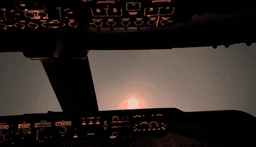
You can take off. You can climb. You can cruise at FL350 and manage your fuel and your FMC and your autopilot with reasonable confidence. Then the descent starts, the weather goes to hell, and you need to find a runway that you cannot see through a grey wall of cloud and rain. This is where it falls apart for most sim pilots.
The ILS approach is the single most important skill in instrument flying. It is the thing that gets you on the ground when the ceiling is 200 feet and you cannot see anything until you are seconds from touchdown. It is also, once you understand how it works, a completely learnable and repeatable procedure. There is nothing magical about it. The system tells you exactly where to go. Your job is to follow the needles.
Want to hand-fly the ILS? A coupled approach is easy. Flying it manually without autopilot is a different skill entirely. Drill localizer and glideslope corrections in our free browser ILS Trainer before you take it into the sim.
This guide covers the ILS approach from the ground up: what the system is, how to read the chart, how to set it up in your aircraft, how to fly it with the autopilot, how to fly it by hand, and what to do when it goes wrong. It works for any aircraft in MSFS 2024 — from a Cessna 172 to a PMDG 737 to a Fenix A320.
Affiliate disclosure: This guide contains affiliate links. If you purchase through these links, SimTuts earns a small commission at no extra cost to you. We only recommend products we genuinely believe improve the flight sim experience.
Want to test yourself as you go? Our free approach plate quiz drills the values you'll brief in this guide — localiser frequency, decision altitude, missed approach.
What an ILS Actually Is
ILS stands for Instrument Landing System. It is a ground-based radio system installed at an airport that provides two things: lateral guidance (left/right of the runway centreline) and vertical guidance (above/below the correct descent path). That is all it does. It draws an invisible line in the sky that leads straight to the touchdown zone, and your instruments show you where you are relative to that line.
The Localizer
The localizer provides lateral guidance — it tells you whether you are left or right of the runway extended centreline. It transmits on a VHF frequency (between 108.10 and 111.95 MHz) and has a usable range of about 18 nautical miles from the runway. The signal gets narrower as you get closer to the runway, which means your corrections need to be smaller and more precise the closer you get.
On your instruments, the localizer shows as a vertical needle (or diamond) on the CDI or PFD. Needle left of centre means the runway centreline is to your left — fly left to correct. Needle right means the centreline is to your right. When the needle is centred, you are on the centreline.
The localizer beam is typically about 5 degrees wide at full deflection, which means at 10 miles from the runway, a full-scale deflection represents roughly half a mile of offset. At 2 miles out, full deflection is only about 500 feet. This is why the needle gets more sensitive as you approach — the same physical needle movement represents a much smaller distance error.
The Glideslope
The glideslope provides vertical guidance — it tells you whether you are above or below the correct descent path. Most ILS glideslopes are set at 3 degrees, which translates to roughly 300 feet of altitude lost per nautical mile. Some airports with terrain obstructions use steeper glideslopes (3.5 degrees or more), but 3 degrees is the standard.
On your instruments, the glideslope shows as a horizontal needle (or diamond). Needle above centre means the correct path is above you — you are too low. Needle below centre means you are too high. Like the localizer, the glideslope signal gets more sensitive as you approach the runway.
The glideslope antenna is positioned about 750-1,250 feet down the runway from the threshold, next to the touchdown zone. This is important — it means the glideslope is calibrated to put you over the threshold at roughly 50 feet, descending to the touchdown zone. You do not aim for the numbers; the glideslope puts you exactly where you need to be.
Marker Beacons
Traditional ILS installations include marker beacons — small transmitters positioned along the approach path that trigger annunciations in the cockpit as you fly over them:
| Marker | Distance from Runway | Colour | Purpose |
|---|---|---|---|
| Outer Marker (OM) | 4-7 NM | Blue | Marks the final approach fix, glideslope intercept point |
| Middle Marker (MM) | ~0.5 NM | Amber | Near decision altitude on a Category I ILS |
| Inner Marker (IM) | At threshold | White | Used for Category II/III approaches (rare) |
In practice, many real-world airports have decommissioned their marker beacons and replaced them with DME (distance measuring equipment) or GPS fixes. MSFS 2024 simulates marker beacons at many airports, and you will hear the audio tones — a series of dashes for the outer marker, alternating dots and dashes for the middle marker.
ILS Categories
Not all ILS approaches are created equal. The category determines how low you can go:
| Category | Decision Height | Runway Visual Range |
|---|---|---|
| CAT I | 200 ft AGL | 550m / 1,800 ft |
| CAT II | 100 ft AGL | 300m / 1,000 ft |
| CAT IIIa | 50 ft AGL | 200m / 700 ft |
| CAT IIIb | <50 ft or none | 75m / 250 ft |
| CAT IIIc | No minimum | No minimum |
For most flying in MSFS 2024, you will fly CAT I approaches. The decision altitude is typically 200 feet above the runway — meaning if you reach 200 feet and cannot see the runway environment, you go around. CAT II and III approaches require specific aircraft equipment, crew training, and airport facilities. In the sim, you can practice these if your aircraft supports autoland (the PMDG 737, Fenix A320, and several others do), but CAT I is the standard.
How the Frequencies Work
Every ILS has a unique frequency assigned to it. When you tune this single frequency on your NAV radio, you receive both the localizer and the glideslope — they are paired. You do not need to tune two separate frequencies.
For example, the ILS for runway 27L at London Heathrow (EGLL) might be on frequency 109.50. Tune 109.50 on your NAV1 radio, and you get both lateral and vertical guidance for that specific runway.
The ILS also transmits a Morse code identifier that you can listen to for verification. If the chart says the identifier is "I-LL" and you hear "I-LL" in Morse on the audio panel, you have the right ILS tuned. In the sim, this step is easy to skip, but it is worth checking at least once to build the habit.
Reading Approach Plates
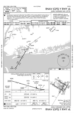
An approach plate (or approach chart) is the diagram that tells you everything you need to know about a specific instrument approach to a specific runway. You cannot fly an ILS properly without one. Opening the plate and briefing it before you start descending is the single biggest thing you can do to reduce your workload during the approach.
MSFS 2024 includes built-in approach charts accessible through the EFB (Electronic Flight Bag) in the cockpit. These are simplified versions, but they contain the essential information. For more detailed charts, use Navigraph or the freely available FAA charts for US airports (available at the FAA's DTPP page).
The Key Information
Here is what to look for on an ILS approach plate. You do not need to understand every symbol — just these essentials:
Approach name and runway: At the top. For example, "ILS or LOC RWY 27L" means this chart covers the ILS approach (and the localizer-only approach) to runway 27L.
ILS frequency and course: Usually shown prominently near the plan view. The frequency is what you tune on your NAV radio. The course is the magnetic bearing of the final approach — this number goes into your course selector (OBS) or is set automatically by the FMS. For runway 27L, the final approach course is 274 degrees (not always exactly the runway heading — there can be a few degrees of difference).
Final Approach Fix (FAF): This is the point where the final descent begins. On an ILS, the FAF is typically the point where you intercept the glideslope at the published altitude. On the profile view, it is marked with a Maltese cross. The altitude at the FAF tells you how high you should be when you start tracking the glideslope down.
Decision Altitude / Decision Height (DA/DH): This is the lowest you can descend on the approach. If you reach this altitude and do not have the runway environment in sight, you execute a missed approach (go-around). For a CAT I ILS, this is typically 200 feet above the touchdown zone elevation. The chart publishes both the DA (referenced to mean sea level) and the DH (referenced to the runway threshold, which is what your radar altimeter reads).
Glideslope angle: Usually 3.00 degrees, shown on the profile view. Occasionally you will see 3.25 or 3.5 degrees at airports with terrain considerations.
Minimum altitude at each fix: The profile view shows the altitude you should be at for each waypoint on the approach. These are minimums — you must be at or above these altitudes at each fix.
Missed approach procedure: Published on the chart, usually in text at the top and graphically on the plan view. It tells you what to do if you cannot land: climb to a specific altitude, turn to a heading or fly to a fix, and then hold or proceed as directed by ATC.
A Quick Example
Imagine you are looking at the ILS RWY 28R approach plate for San Francisco (KSFO):
- ILS Frequency: 111.70
- Final Approach Course: 284 degrees
- Glideslope Angle: 3.00 degrees
- FAF (AXMUL): Cross at 1,800 feet
- Decision Altitude: 213 feet MSL (200 feet above TDZE of 13 ft)
- Missed Approach: Climb to 3,000 feet on the SFO VOR/DME R-281 to VIKYU and hold
Before you start the approach, you should know all of these numbers. Say them out loud during your approach briefing: "ILS 28 Right, frequency one-one-one-seven-zero, inbound course two-eight-four, decision altitude two-one-three, missed approach — climb three thousand on the San Francisco R-two-eight-one to VIKYU and hold."
This takes 15 seconds and transforms the approach from a reactive scramble into a planned procedure.
Flying ILS in a GA Aircraft — Raw Data
If you are flying a Cessna 172, Bonanza, or another general aviation aircraft without an FMS, you fly the ILS using raw data — the CDI needles on your NAV instruments. This is actually the best way to learn the ILS, because you understand exactly what is happening without the abstraction of automation.
Setup
-
Tune the ILS frequency on your NAV1 radio. Use the frequency from the approach plate. Make sure you are tuning NAV1, not NAV2 (though NAV2 works too — just ensure your CDI or HSI is displaying the correct source).
-
Set the inbound course on your OBS (Omni Bearing Selector). This is the course from the approach plate, not the runway heading. For example, if the approach plate says "ILS RWY 28R, course 280," set 280 on your OBS. On an HSI (Horizontal Situation Indicator), the compass card stays slaved to your heading; setting the course rotates the course pointer (the arrow across the card) to 280.
-
Identify the ILS. Listen for the Morse code identifier on your audio panel. This confirms you have the right station tuned.
-
Check for glideslope indication. The glideslope needle should appear on your CDI or PFD. If it shows a flag or no indication, you may be too far from the airport, out of the coverage area, or have the wrong frequency.
Flying the Approach
Intercept: Fly toward the final approach course at an angle of 30-45 degrees. If the inbound course is 282 degrees, ATC might vector you on a heading of 310 or 320 to intercept from the left, or 240-250 to intercept from the right. Watch the localizer needle — as it starts moving toward the centre, begin your turn to the inbound course.
Localizer tracking: Once established on the localizer, keep the vertical needle centred. The corrections are small — 2 to 5 degrees of heading change at a time. If the needle is slightly left, turn left 2-3 degrees. When it starts coming back to centre, turn back to the inbound course. The key is to make small corrections early rather than large corrections late.
Glideslope intercept: The glideslope needle will start high on your instrument (meaning the glideslope is above you). As you approach the glideslope intercept point (typically at the published altitude near the FAF), the needle will start to come down. When it centres, begin your descent. A standard 3-degree glideslope requires roughly 450-600 feet per minute descent rate at typical approach speeds (90-120 knots for GA aircraft).
Descent rate rule of thumb: Multiply your groundspeed by 5 to get the approximate descent rate needed for a 3-degree glideslope. At 90 knots groundspeed: 90 x 5 = 450 fpm. At 120 knots: 120 x 5 = 600 fpm. Adjust for wind — headwind means lower groundspeed and lower descent rate; tailwind means the opposite.
Power management: The glideslope demands a constant angle, not a constant descent rate. As your speed changes, you need to adjust power to maintain the correct descent rate while keeping the glideslope needle centred. This is where it gets busy: you are simultaneously managing heading (localizer), descent rate (glideslope), speed (power), and configuration (flaps and gear if applicable). Welcome to instrument flying.
At decision altitude: When your altimeter reads the decision altitude, look up. If you can see the runway environment — approach lights, runway lights, the runway itself — continue to land. If you cannot see it, execute the missed approach immediately.
Tips for Raw Data ILS
- Trim, trim, trim. A well-trimmed aircraft is infinitely easier to fly on approach. If you are fighting the yoke or stick the whole way down, you are not trimmed properly.
- Fly the needles, not the runway. Until you reach decision altitude, your references are the CDI needles, not what is out the window. Trust the instruments.
- Anticipate, do not chase. If the localizer needle is slowly drifting right, apply a small correction now. Do not wait until it is at the edge of the scale and then make a huge correction — you will overshoot the other way.
- Start configured early. In a Cessna 172, have your first notch of flaps in by the FAF. In a retractable-gear aircraft like the Bonanza, gear down before the glideslope intercept. Getting the aircraft configured early means one less thing to manage during the descent.
Setting Up the Approach in the PMDG 737 (Boeing CDU)
The PMDG 737 for MSFS 2024 simulates the Boeing CDU (Control Display Unit) in detail. Setting up an ILS approach involves telling the FMC which approach you want, which loads the correct course and fixes, and then tuning the ILS frequency. Here is the step-by-step workflow.
Loading the Approach via the CDU
Step 1: Open the DEP/ARR page
Press the DEP ARR button on the CDU. You will see your departure and destination airports. Select the line next to your destination airport (right side). This opens the arrivals page.
Step 2: Select the STAR (if you have not already)
If you haven't loaded a Standard Terminal Arrival Route, do this first. Select the appropriate STAR for your direction of arrival. The STAR feeds you from the en-route phase to the approach transition.
Step 3: Select the approach
Scroll through the available approaches for the destination. You will see entries like:
ILS 28R
ILS 28L
RNAV (GPS) 28R
VOR 28R
Select the ILS approach for your intended runway. The CDU may then ask you to select a transition — this is the feeder fix that connects the STAR to the final approach course. Common transitions are named after the initial approach fix (IAF), such as a VOR or intersection. If in doubt, select the transition that aligns with your STAR or select "vectors" if ATC will give you headings to intercept the final approach course.
Step 4: Execute the changes
After selecting the approach and transition, you will see the changes on the LEGS page in white (modified). Press EXEC (Execute) to confirm. The approach waypoints are now loaded into the flight plan.
That white-then-EXEC sequence is the part people get wrong, because a modification you never executed looks almost identical to one you did. Practise the key presses on our browser 737 CDU in The EXEC Light — free — and if you want the whole approach build end to end, the Premium Approach Numbers (APPROACH REF) scenario runs it at EGLL.
Tuning the ILS Frequency
The PMDG 737 can auto-tune the ILS frequency when the approach is loaded in the FMC and you are close enough to the airport. However, it is good practice to verify or manually set the frequency:
Manual tuning: On the radio panel (above the CDU), use the NAV1 frequency knobs to dial in the ILS frequency from the approach plate. The inner knob changes decimals, the outer knob changes whole numbers.
Auto-tune verification: When the ILS is loaded in the FMC and auto-tune is active, the frequency should appear on the NAV1 radio display. Cross-check this with your approach plate.
Setting the Course
The inbound course should be set on the MCP (Mode Control Panel, the glareshield panel). Find the COURSE knob on the left side (for the captain's side) and dial in the published final approach course. If the approach is loaded in the FMC, the course may already be set — verify it matches the plate.
This course setting is critical. If it is wrong, the autopilot will not capture the localizer correctly, or it will try to fly the wrong direction on the localizer signal (a "back course" capture, which is bad).
The PMDG 737 Approach Checklist (Abbreviated)
Before intercepting the localizer, verify:
| Item | Setting |
|---|---|
| ILS frequency | Tuned and identified on NAV1 |
| Inbound course | Set on MCP course selector |
| Approach loaded | Verified on LEGS page |
| Decision altitude | Set in MCP altitude window (or noted for reference) |
| Missed approach altitude | Known and ready to set |
| Autobrake | Set (typically position 3 for a normal landing) |
| Speedbrake | Armed |
| Landing flaps | Briefed (typically flaps 30 or 40) |
Setting Up the Approach in the Fenix A320 (Airbus MCDU)
The Fenix A320 for MSFS 2024 uses the Airbus MCDU and flight management philosophy, which is different from Boeing in its interface but achieves the same result. Here is the workflow.
Loading the Approach via the MCDU
Step 1: Open the ARRIVAL page
Press the ARRIVAL key on the MCDU (or navigate via F-PLN > ARRIVAL). This opens the arrivals page for your destination airport.
Step 2: Select STAR and approach
The Airbus MCDU presents the STAR and approach selection on related pages. Select your STAR first (if not already loaded), then select the approach type. You will see options like:
ILS28R
LOC28R
RNAV28R
Select the ILS for your intended runway.
Step 3: Select the transition (VIA)
Like Boeing, the Airbus asks for a transition. Select the appropriate one based on your arrival direction, or "NO VIA" if ATC will vector you to the final approach course. In the Airbus world, "vectors" (MANUAL TERMINATION / CF leg) is common — the FMS will draw a dashed line from your last waypoint to the final approach course, and you fly headings from ATC or yourself until intercepting.
Step 4: Insert the arrival
Press the INSERT prompt on the MCDU. The approach is now loaded into the flight plan. You can verify it by pressing the F-PLN key and scrolling through the waypoints — you should see the approach fixes, glideslope intercept point, and the runway.
If you want to rehearse that selection without loading a sim, the Premium ILS RWY 27L at Atlanta scenario walks the same ARRIVAL → APPR → VIA → INSERT sequence on our browser A320 MCDU, with feedback on each entry. The free INIT Page Basics is the place to start if the MCDU itself is unfamiliar.
ILS Frequency and Course in the A320
The Fenix A320 auto-tunes the ILS frequency when the approach is loaded and the aircraft is within range. The frequency appears on the PFD near the localizer/glideslope indicators. You can verify it on the RADIO NAV page of the MCDU:
Press RADIO NAV on the MCDU. The ILS frequency and course should be displayed. If the frequency is wrong or missing, you can manually enter it here. Typing an ILS frequency and course by hand on that page is the Radio Navigation Setup scenario in our MCDU trainer — free.
The inbound course is also set automatically when the approach is loaded. It appears on the PFD next to the localizer diamond. Verify it matches the chart.
APPR Phase in the Airbus
The Airbus has a distinct APPR phase in its flight management that activates during the approach. Key things to know:
- PERF APPR page: Accessible via the PERF key, then navigate to the APPR page. Here you enter (or verify) the decision height, approach speed (Vapp), landing configuration, and wind data for the approach. The FMC uses these to calculate the managed approach speed.
- Vapp: This is the target approach speed. It is typically Vref (reference landing speed) plus a wind correction. The Airbus calculates this automatically if you have entered the winds. You can override it manually.
- Decision Height: Enter the DH from the approach plate. This sets the DH bug on the PFD and triggers the "MINIMUM" callout at the correct altitude.
The PERF APPR page is worth drilling on its own, because a wrong or missing entry here is silent until the aeroplane will not slow down: the Premium Approach Numbers (PERF APPR) scenario sets QNH, wind, DH and the landing configuration for EGLL 27R.
The Fenix A320 Approach Checklist (Abbreviated)
| Item | Setting |
|---|---|
| ILS frequency | Auto-tuned and verified on RADIO NAV page |
| Inbound course | Verified on PFD |
| Approach loaded | Verified on F-PLN page |
| DH/DA | Entered on PERF APPR page |
| Vapp | Verified on PERF APPR page |
| Autobrake | Set (typically MED for a normal landing) |
| Ground spoilers | Armed |
| Landing config | Briefed (typically CONF FULL or CONF 3) |
Flying the ILS with Autopilot
This is the standard method for ILS approaches in airliners. The autopilot does the tracking; you manage the setup, configuration, and monitoring. Understanding exactly what the autopilot is doing — and what it is waiting for — is the difference between a smooth approach and an autopilot that does something unexpected.
The Sequence
The ILS approach with autopilot follows a predictable sequence. Learn this and it becomes second nature.
1. Get established on the intercept heading
Before you can capture the localizer, you need to be flying toward it. ATC (or your own navigation) will have you on a heading that intercepts the final approach course at an angle, typically 30-45 degrees. Set this heading on the MCP (Boeing) or FCU (Airbus).
In the 737: Use the HDG SEL knob on the MCP. Turn it to the intercept heading and ensure the heading mode (HDG SEL) is active on the flight mode annunciator (FMA) at the top of the PFD.
In the A320: Use the HDG knob on the FCU. Pull for selected heading mode. The FMA will show HDG on the lateral mode.
2. Set the altitude at or above the glideslope intercept altitude
You need to be level (or descending to) the published altitude for the glideslope intercept. If the approach plate says "intercept the glideslope at 3,000 feet," make sure your altitude target is set to 3,000 feet and you are level at that altitude when you reach the intercept point.
Being above this altitude is the number one reason the glideslope does not capture. If you are at 4,000 feet when the glideslope intercept point is at 3,000, the glideslope needle will be below you and the autopilot will never capture it — it only captures from below.
3. Arm the approach mode
This is the critical step that many sim pilots forget or time incorrectly.
In the 737: Press the APP button on the MCP. This arms both the localizer and glideslope capture modes. On the FMA, you will see:
- LOC (armed, shown in white) — waiting to capture the localizer
- G/S (armed, shown in white) — waiting to capture the glideslope
The autopilot is now listening to the ILS signal and will automatically capture when it intercepts.
In the A320: Press the APPR button on the FCU. This arms the approach mode. On the FMA, you will see:
- LOC (armed, in blue) — waiting to capture
- G/S (armed, in blue) — waiting to capture
4. LOC capture
As you approach the localizer centreline, the autopilot detects the localizer signal moving toward centre and begins turning to track the inbound course. On the FMA, LOC changes from armed (white/blue) to captured (green). This typically happens a few miles before you reach the centreline, as the autopilot smoothly rolls into the intercept.
At this point, the aircraft is tracking the localizer but still flying level — it has not started descending yet. The glideslope mode remains armed, waiting for the aircraft to intercept the glideslope from below.
5. G/S capture
As you continue inbound on the localizer, you will approach the glideslope. The glideslope needle, which was above centre (glideslope above you), will start to come down. When it centres, the autopilot captures the glideslope and begins a controlled descent. On the FMA, G/S changes from armed to captured (green).
Now the autopilot is tracking both the localizer and glideslope. Your descent rate will be approximately 700-800 fpm in a GA aircraft, or around 700 fpm at 140 knots in an airliner, varying with groundspeed.
6. Configure for landing
With the autopilot flying the approach, you now configure the aircraft:
In the 737:
- Flaps: Extend sequentially. Flaps 1, then 5, then 15, then 25, then 30 (or 40 for full landing flaps). Each extension changes the reference speed — the target speed decreases as flaps extend.
- Gear: Down when established on the glideslope and at the appropriate speed (typically below 270 knots for gear extension, though with flaps already out you will be slower). Many pilots put the gear down at the glideslope intercept or slightly before.
- Speed: Set the target speed on the MCP or let VNAV manage it if you are using managed speed.
In the A320:
- Flaps: Extend in sequence. CONF 1, then 2, then 3, then FULL. The Airbus manages speed automatically in managed mode — extending flaps will cause the target speed to decrease smoothly.
- Gear: Down when established on the glideslope, typically commanded by the pilot at around 2,000 feet above airport elevation.
- Speed: In managed mode, the A320 will decelerate to Vapp as you extend flaps. Verify the speed target on the PFD speed tape.
7. Monitor the approach
This is your primary job with the autopilot engaged. Watch:
- The FMA: Confirm LOC and G/S (or LAND mode in the A320, which activates automatically below a certain altitude) remain captured. If anything changes unexpectedly, be ready to intervene.
- The localizer and glideslope diamonds: Even with the autopilot flying, confirm the diamonds stay centred. An off-centre diamond with the autopilot engaged means something is wrong — possibly a wrong frequency, a failed signal, or an autopilot malfunction.
- Speed: Confirm the aircraft is at the correct approach speed. Too fast means unstable approach, too slow means risk of stall (especially with landing flaps).
- Altitude: Watch your altitude against the published minimums. Know your decision altitude and be ready to act when you reach it.
8. At decision altitude
When the radio altimeter (or barometric altimeter) reaches your decision altitude:
- Can see the runway environment: Call "landing" and either let the autopilot continue to autoland (if capable and conditions warrant) or disconnect the autopilot and hand-fly the last 200 feet to touchdown.
- Cannot see the runway: Call "go around" and immediately execute the missed approach (covered later in this guide).
Armed vs Captured — Why This Matters
Understanding the difference between armed and captured modes prevents one of the most common autopilot-related mistakes on approach.
Armed means the autopilot is ready to capture the signal, but has not yet intercepted it. The mode is displayed but not active. The autopilot is still following its current mode (heading, for example) and simultaneously monitoring the ILS signal.
Captured means the autopilot has intercepted the signal and is actively tracking it. The mode is now in control of the aircraft's lateral path (LOC) or vertical path (G/S).
The transition from armed to captured happens automatically — you do not need to press anything additional. But if the conditions are not right (wrong frequency, wrong course, too far away, too high for glideslope, approaching from the wrong angle), the mode will remain armed forever and never capture. This is a silent failure. The autopilot does not warn you that it has not captured — it just keeps flying the heading. You need to be watching the FMA.
Signs that the mode is not going to capture:
- You have passed through the localizer centreline and LOC is still showing armed
- You are past the glideslope intercept point and G/S is still armed
- The localizer or glideslope diamonds are showing full deflection despite APP/APPR being armed
If any of these happen, something is wrong with your setup. Check frequency, course, and position.
Flying the ILS Manually
There is a good argument that every sim pilot should fly a few ILS approaches manually before relying on the autopilot. When you hand-fly the ILS, you develop an intuitive understanding of how the needles respond, what corrections feel like, and how the aircraft behaves on approach. This understanding makes you a better monitor of the autopilot later.
When to Hand-Fly
Some scenarios where you might hand-fly the ILS:
- In a GA aircraft without an autopilot (Cessna 172, Bonanza)
- For practice — building skills and understanding
- Below decision altitude — many airline pilots disconnect the autopilot at 500-1,000 feet and hand-fly the landing
- Autopilot malfunction — if the autopilot fails on approach, you need to be able to continue manually
- Personal preference — some sim pilots simply prefer hand-flying approaches
The Technique
Manual ILS flying is about two things happening simultaneously: tracking the localizer (heading corrections) and tracking the glideslope (pitch and power corrections). Here is how to break it down.
Localizer Tracking
The localizer needle moves left and right. Your job is to keep it centred. The technique:
- Fly the inbound course heading. If the course is 282 degrees, start by flying 280.
- Watch the needle. If it drifts left, you are right of course. Turn left by 5-10 degrees to intercept. So fly 270-275.
- As the needle starts to re-centre, turn back toward the inbound course. Do not fly all the way back to 280 — turn to something like 278 or 279 to account for wind drift.
- Bracket the wind correction angle. Over a few corrections, you will find the heading that keeps the needle centred. This is the inbound course plus or minus a wind correction. In a crosswind from the right, you might find that 276 degrees keeps you on the centreline when the course is 280. This 4-degree correction is your wind correction angle.
The key principle: the correction heading must be toward the needle, but the amount of correction decreases as you get closer. Far from the runway, you might use 10-degree corrections. Inside the FAF, corrections should be 1-2 degrees maximum.
Glideslope Tracking
The glideslope needle moves up and down. Your job is to keep it centred using a combination of pitch and power.
- Intercept the glideslope from below. You should be level at the glideslope intercept altitude. As the needle comes down to the centre, lower the nose and reduce power to begin descending.
- Set an initial descent rate. Use the groundspeed x 5 rule. At 130 knots groundspeed, start with approximately 650 fpm. Adjust from there.
- If the needle rises (glideslope going above you): You are below the glideslope. Reduce your descent rate — raise the nose slightly or add a small amount of power. Do not over-correct. A 50-100 fpm change is usually enough.
- If the needle drops (glideslope going below you): You are above the glideslope. Increase your descent rate — lower the nose slightly or reduce power a touch.
- Stay ahead of the needle. The glideslope gets more sensitive as you get closer. Corrections at 8 miles out are gentle. Corrections at 2 miles out need to be immediate and precise.
Power and Pitch — The Relationship
On a stabilised ILS approach, pitch controls your speed and power controls your descent rate. This is the opposite of what intuition tells you during normal flight, and it trips people up.
Here is why: on a fixed glideslope angle, if you add power without changing pitch, the aircraft accelerates slightly and then climbs above the glideslope (because more speed = more lift). If you raise the nose without changing power, the aircraft decelerates and eventually sinks below the glideslope.
The practical application:
- Too fast, on glideslope: Raise the nose slightly. Speed will decrease. Then reduce power slightly to maintain the glideslope.
- Too slow, on glideslope: Lower the nose slightly. Speed will increase. Then add power slightly to maintain the glideslope.
- On speed, above glideslope: Reduce power. The aircraft will descend back to the glideslope. You may need a tiny nose-down input to prevent slowing down.
- On speed, below glideslope: Add power. The aircraft will climb back to the glideslope.
In practice, these corrections blend together and become instinctive after enough approaches. The first 10 manual ILS approaches will feel like juggling. By approach 50, you will be making corrections without thinking about them.
Crosswind Technique
If there is a crosswind on the approach, you have two options:
Crab method: Maintain a wind correction angle to keep the localizer centred. As you approach the runway, kick the rudder to align with the centreline just before touchdown. This is the standard method for airliners and large aircraft.
Wing-low method: Lower the upwind wing to counteract drift, and use opposite rudder to keep the nose aligned with the runway. This is common in GA aircraft and gives you a runway-aligned approach all the way down.
In MSFS 2024, crosswinds on approach are where the sim's improved weather system really shines. Gusty conditions and wind shear near the ground create realistic challenges that make hand-flying approaches genuinely demanding.
Disconnect and Transition
If you are using the autopilot for most of the approach and plan to disconnect for the landing, the transition matters:
- Disconnect at a planned altitude. Common choices are 1,000 feet AGL (early, more practice) or 500 feet AGL (late, less exposure). Below 500 feet is risky for disconnecting in bad weather — you have very little time to stabilise if something goes wrong.
- Press the disconnect button. On the 737, it is the red button on the yoke. On the A320, press the red sidestick button or the A/P disconnect pushbutton. An autopilot disconnect warning will sound — silence it with a second press.
- Hold what you have. Do not immediately make corrections. The autopilot was trimmed — just hold the pitch and bank. The aircraft should continue tracking smoothly.
- Make minor corrections as needed. Now you are hand-flying with the needles centred from the autopilot's work. Maintain the localizer and glideslope as described above.
Get flight sim tips in your inbox
New guides, checklists, and tips — no spam. Unsubscribe any time.
Common Mistakes and How to Fix Them
Every one of these mistakes has ruined approaches for experienced sim pilots. Some of them are easy to make even when you know better.
My autopilot blows through the localizer in the turn
The fix: intercept the localizer at 30-45 degrees, never more. If the inbound course is 282 degrees, your intercept heading should be between 235 and 250 (from the south) or between 310 and 325 (from the north). If you find yourself at 90 degrees or more, extend outbound to create a shallower angle, or ask ATC for a wider vector.
What you see: you are on a heading 90 degrees off the inbound course (or more), the autopilot starts to turn when the localizer comes alive, and the aircraft sails through the centreline because it cannot turn fast enough.
Why it happens: ATC gave you a heading that results in a steep intercept, or you set up your own approach and aimed straight at the airport rather than positioning for a shallow intercept.
My autopilot won't capture the glideslope — I'm stuck above it
The fix: be at or below the published glideslope intercept altitude before you reach the intercept point. If the chart says the glideslope intercept altitude is 3,000 feet at the FAF, you must be at 3,000 feet (or slightly below) when you get there. If you are high, use speed brakes, increase your descent rate, or ask ATC for a longer vector to give yourself more time to descend.
What you see: you press APP/APPR, the localizer captures fine, the FMA shows G/S armed — and the glideslope never captures. You fly straight through the intercept point still at altitude.
Why it happens: you are above the glideslope. The autopilot only captures the glideslope from below — if the beam is beneath you, the autopilot will not dive down to catch it. Being above this altitude is the number one reason the glideslope does not capture.
My autopilot captures the glideslope but can't stay on it
The fix: be below 200 knots (ideally below 180 in an airliner) by the glideslope intercept point. In the 737, configure flaps 5 or 15 before glideslope intercept. In the A320, CONF 2 is typical by this point. In a GA aircraft, approach speed should already be set.
What you see: the glideslope captures, then the aircraft descends through it or porpoises around it, and the autopilot never settles.
Why it happens: you are too fast. At 250 knots you need a far higher descent rate to hold a 3-degree glideslope than at 160 knots. The autopilot struggles, and hand-flying it is nearly impossible.
My autopilot ignored the ILS completely and flew past the runway
The fix: arm approach mode — press APP (Boeing) or APPR (Airbus) — and confirm LOC and G/S appear in the armed column of the FMA. If they do not appear, something else is wrong; do not continue expecting a capture.
What you see: you are on a perfect intercept heading, at the right altitude, with the right frequency tuned, and the aircraft flies straight through the localizer. The autopilot happily continues on its heading.
Why it happens: you never pressed APP or APPR. The autopilot is in heading mode and has no idea there is an ILS signal to capture. Put "Approach mode — armed" in your approach checklist and it stops happening.
I have no ILS needles at all — no localizer, no glideslope
The fix: check the NAV radio and the CDI source before anything else. Verify the frequency is on the radio the display is showing, and that the CDI/PFD source is the ILS and not GPS. In the 737, check the PFD NAV source selector. In the A320, the PFD switches to ILS mode automatically when the approach is loaded. In a GA aircraft, make sure the CDI source button is set to VLOC or NAV, not GPS.
What you see: the CDI shows no signal, or the localizer seems to point at the wrong runway, and the glideslope diamond is absent entirely.
Why it happens: several possible causes:
- You tuned the frequency on NAV2 but your CDI/HSI is displaying NAV1
- You tuned a VOR frequency instead of the ILS frequency
- The FMS is overriding your manual NAV radio tuning
- The CDI source switch is set to GPS instead of NAV/LOC
I reached minimums and still couldn't see the runway
The fix: go around. At decision altitude you either see the runway environment or you fly the missed approach — there is no "almost there". Set the DA as a bug on your altimeter or enter it in the aircraft's systems so you get an audible callout. When you hear "MINIMUMS", look up. If you do not see approach lights, runway lights or the runway surface, push the throttles forward.
What you see: you are focused on the instruments, the altimeter hits 200 feet, and the temptation is to keep descending. Pilots who give in to it land without ever seeing the runway, or fly into terrain that was not where they expected the runway to be.
Why it happens: target fixation. You have been working hard to keep the needles centred, and throwing that away with a go-around is psychologically difficult.
I arrive at the final approach fix too high and too fast to configure
The fix: start configuring early. A general sequence for airliners:
- By glideslope intercept: At least approach flaps (Flaps 15 in the 737, CONF 2 in the A320), gear down or coming down
- By 1,000 feet AGL: Fully configured — landing flaps, gear down, final approach speed
- Stable approach criteria: By 1,000 feet in IMC (or 500 feet in VMC), you should be: on speed (Vref + correction), on glideslope, on localizer, in landing configuration, at the correct descent rate. If any of these are not met, go around.
What you see: you reach the FAF with gear up, flaps clean and speed too high, then try to extend everything at once while descending on the glideslope. The aircraft is completely unstable by 1,000 feet.
I keep S-turning across the localizer
The fix: make a correction half the size of the error, and inside the FAF keep heading changes to 1-3 degrees. If the needle is 1 dot off, a 2-3 degree heading change is enough. Wait for it to take effect. If it is not enough, add another 1-2 degrees. Patience is a skill.
What you see: the localizer needle moves left one dot, so you make a 20-degree heading change. It swings to the right, so you make a 20-degree change the other way. You are now flying S-turns across the centreline.
Why it happens: over-correction — large inputs that are not taken out again quickly enough.
Decision Altitude and the Missed Approach
The missed approach is not optional and it is not a failure. It is a planned procedure that is part of every ILS approach. You brief it before the approach so that when you need it, the action is automatic.
At Decision Altitude
When you reach the decision altitude (typically 200 feet above the runway for a CAT I ILS), you make a binary decision:
Continue to land if you can see any of the following:
- The approach lighting system
- The runway threshold
- The runway markings
- The runway lights
- The touchdown zone or its markings/lights
- The runway itself
You do not need to see the entire runway. A view of the approach lights is sufficient to continue.
Go around if you cannot see any of those things. There is no third option. Do not descend below DA hoping it will get better. It might, but that is not a plan.
Executing the Go-Around
The go-around procedure is immediate and assertive:
In any aircraft:
- Power: Advance to go-around thrust. In the 737, push the TOGA switches (takeoff/go-around, on the throttle). In the A320, push the thrust levers to the TOGA detent. In a GA aircraft, push the throttle full forward.
- Pitch: Raise the nose to a climb attitude. In an airliner, 15 degrees nose up is typical for the initial rotation. In a GA aircraft, climb attitude.
- Flaps: Retract one notch initially. In the 737, if you are at flaps 30, retract to flaps 15. In the A320, the flight director will guide you.
- Gear: Retract when you have a positive rate of climb.
- Fly the missed approach procedure. Follow the published instructions — climb to the specified altitude, turn to the heading or navigate to the fix, and hold or proceed as directed.
In the 737 specifically:
- Press the TOGA switches. This sets go-around thrust and commands the flight director to show a climb.
- Follow the flight director bars.
- The FMA will show TOGA/TOGA and GA (go-around).
- Retract flaps on schedule as speed increases.
In the A320 specifically:
- Push thrust levers to TOGA. The autopilot (if still engaged) commands a go-around. SRS (Speed Reference System) mode engages for pitch guidance.
- The FMA shows SRS / GA TRK (go-around track).
- Follow the flight director. The aircraft manages the initial climb.
- At thrust reduction altitude, pull the thrust levers back to the CL (climb) detent.
After the Go-Around
Once you are climbing and safe, you have options:
- Try the approach again. Request vectors from ATC for another ILS approach. This is the most common choice.
- Divert to an alternate. If the weather is below minimums and not improving, go to your alternate airport.
- Hold and wait. If the weather is expected to improve, you can hold at a published holding fix and try again later.
In MSFS 2024, the built-in ATC will generally offer vectors for another approach if you announce a missed approach. On VATSIM, the controller will give you missed approach instructions and then sequence you back in.
The Role of ATC — In-Sim and VATSIM
MSFS 2024 Built-In ATC
The default ATC in MSFS 2024 will vector you for an ILS approach if you request it. The quality of these vectors varies — sometimes they are excellent, sometimes they will fly you through the localizer or vector you to a runway you did not want. However, for practicing ILS approaches, the built-in ATC is useful because it gives you intercept headings and descend instructions, simulating the workload of a real approach.
When the ATC says "turn left heading 310, maintain 3,000 until established on the localizer, cleared ILS runway 28 Right approach," it is telling you:
- Fly heading 310 (your intercept heading)
- Stay at 3,000 feet until the localizer captures (this is the glideslope intercept altitude)
- You are cleared to fly the ILS approach to runway 28R
Set heading 310, set altitude 3,000, arm APP/APPR mode, and let the system capture. That is the entire procedure.
The built-in ATC's limitations are mostly about non-standard situations. It handles a straightforward approach reasonably well. Where it struggles is in busy traffic, complex arrival procedures, and weather-related deviations.
VATSIM
If you want the real experience of being vectored for an ILS approach, fly on VATSIM. A human controller will sequence you with other traffic, give you headings and altitudes to intercept the ILS, and clear you for the approach. The communication adds another layer of workload, which is exactly what makes real instrument approaches challenging.
VATSIM controllers will also issue speed restrictions on approach, tell you when to expect the approach, and give you missed approach instructions if needed. It is the closest you can get to real IFR operations in a simulator.
For your first few VATSIM ILS approaches, pick a time when the traffic is not too heavy and the controller is not overwhelmed. Listen to the frequency for a few minutes before checking in to understand the flow.
Putting It All Together — A Complete ILS Approach Walkthrough
Here is a full ILS approach from start to finish, assuming you are in an airliner (the same principles apply to GA, just with simpler avionics).
20 minutes before arrival:
- Review the ATIS (Automatic Terminal Information Service) for the destination airport. Note the active runway, weather, and altimeter setting.
- Pull up the approach plate for the ILS approach to the active runway.
- Brief the approach: frequency, course, FAF altitude, decision altitude, missed approach procedure.
During descent: 4. Load the approach and STAR in the FMC/MCDU if not already done. 5. Verify the ILS frequency is tuned and the course is set. 6. Begin slowing down and configuring the aircraft as altitude decreases.
Approach intercept: 7. ATC (or your own navigation) provides an intercept heading and altitude. 8. Set the intercept heading on the MCP/FCU. 9. Set the altitude to the glideslope intercept altitude. 10. Arm the approach mode (APP/APPR). 11. Verify LOC and G/S are armed on the FMA.
Localizer capture: 12. The localizer captures. FMA shows LOC captured. 13. Continue at the assigned altitude, slowing and configuring.
Glideslope capture: 14. The glideslope captures. FMA shows G/S captured. 15. Descent begins. Gear down. Continue extending flaps to landing configuration.
Final approach: 16. By 1,000 feet AGL: fully configured, stable approach confirmed. 17. Monitor: speed, glideslope, localizer, altitude. 18. Listen for callouts: "1,000 feet," "500 feet," "approaching minimums," "MINIMUMS."
Decision altitude: 19. At DA: look up. See the runway? Land. Do not see it? Go around.
Landing: 20. Flare and touchdown. Reverse thrust, brakes, spoilers.
Practice Airports in MSFS 2024
Here are four airports that are excellent for practicing ILS approaches. They have long runways, ILS-equipped primary runways, relatively simple terrain, and the scenery in MSFS 2024 is detailed enough to make the visual transition at decision altitude realistic.
KJFK — John F. Kennedy International, New York
- ILS runways: 4L, 4R, 13L, 22L, 22R, 31L, 31R (multiple options)
- Why it is good: Long runways (over 10,000 feet), flat terrain on approach, iconic airport with great scenery in MSFS 2024. The ILS 22L approach is particularly good for practice — straight-in over the water with clear terrain.
- Weather tip: Set overcast at 500 feet with 3 miles visibility for a realistic CAT I practice.
EGLL — London Heathrow, United Kingdom
- ILS runways: 27L, 27R, 09L, 09R
- Why it is good: Dual parallel ILS approaches on 27L/27R are among the most-used ILS approaches in the world. Flat terrain, long runways, and typically gusty crosswind conditions that make the approach challenging and rewarding.
- Weather tip: Set low overcast with rain and a 15-knot crosswind. Welcome to a typical Heathrow arrival.
KSFO — San Francisco International, California
- ILS runways: 28L, 28R
- Why it is good: The approaches over the San Francisco Bay are spectacular, and the terrain to the west (Pacific Ocean) means a clean approach with no obstacles. The ILS 28R approach is a classic.
- Weather tip: KSFO is known for fog. Set low-visibility conditions with fog at 300 feet for a challenging but realistic scenario.
RJTT — Tokyo Haneda, Japan
- ILS runways: 16L, 16R, 22, 34L, 34R
- Why it is good: Stunning MSFS 2024 scenery, long runways, and approaches over Tokyo Bay. The ILS 34L approach gives you a visual transition over the bay with the city skyline visible. Good for practicing in a different geographic context with different scenery cues.
- Weather tip: Set a 1,000-foot ceiling with moderate rain for a realistic East Asian weather scenario.
Setting Up a Practice Session
The fastest way to practice ILS approaches in MSFS 2024:
- Start in the air. Use the "Set Location" feature in the flight planning screen to place your aircraft at 5,000-6,000 feet, about 15-20 nautical miles from the airport, roughly aligned with the final approach course. This skips the cruise and descent and puts you right at the interesting part.
- Set the weather. Use the custom weather options to create instrument conditions. A 500-foot ceiling with 2 miles visibility is a good starting point. Once you are comfortable, lower the ceiling to 300 or 200 feet.
- Fly the approach. Set up the ILS, intercept, configure, land.
- Repeat. Do 5-10 approaches in a session. Muscle memory develops through repetition, not through single attempts separated by weeks.
Vary the conditions each time: different wind directions, different visibility, different aircraft types. A Cessna 172 ILS at KJFK feels completely different from a PMDG 737 ILS at EGLL, and both teach you different aspects of the same procedure.
Speed and Configuration Reference
The following table gives approximate target speeds for common MSFS 2024 aircraft during an ILS approach. These are guidelines — always use the speeds recommended in the aircraft's documentation or the FMC/MCDU calculated speeds.
| Aircraft | Glideslope Intercept | FAF | Final Approach (Vref + wind) | Typical Descent Rate |
|---|---|---|---|---|
| Cessna 172 | 90 knots | 90 knots | 65-70 knots | 400-500 fpm |
| Bonanza G36 | 110 knots | 100 knots | 80-85 knots | 500-550 fpm |
| King Air 350 | 140 knots | 130 knots | 110-120 knots | 600-650 fpm |
| PMDG 737-800 | 180-160 knots | 160 knots | 135-145 knots (Vref + 5) | 700-750 fpm |
| Fenix A320 | 180-160 knots | 155 knots | 130-140 knots (Vapp) | 700-750 fpm |
The descent rate rule of thumb applies across all aircraft: groundspeed x 5 = approximate descent rate for a 3-degree glideslope. Adjust for headwinds and tailwinds.
MSFS 2024 Specifics
MSFS 2024 brings several improvements that directly affect ILS approaches:
Improved weather engine. The weather model in MSFS 2024 is more dynamic than its predecessor. Cloud layers have realistic tops and bottoms, fog formation is more natural, and wind shear near the ground creates genuine challenges during the final stages of the approach. You will notice the aircraft reacting to turbulence in the cloud layer and potentially getting pushed around as you break out of the overcast.
Better ground handling. The improved ground physics affect the landing rollout after the ILS approach, particularly in crosswind conditions. Runway surface conditions (wet, contaminated) affect braking.
Enhanced avionics. The default aircraft in MSFS 2024 have improved avionics simulations. The Cessna 172 G1000 panel, for example, has better ILS display behaviour than in MSFS 2020. Third-party aircraft like the PMDG 737 and Fenix A320 remain the gold standard for systems fidelity, but the defaults are more capable than before.
Live weather. Using real-world weather (live weather option) means you will encounter actual weather conditions at your destination. This is the ultimate ILS practice — you do not know what you will get until you get there, just like a real pilot. Check the METAR for your destination before departure, plan your approach plate and minimums accordingly, and see if you can get in.
Gear That Helps
A note on hardware: A stable ILS comes down to smooth, small inputs on the controls — holding the localiser and glideslope is far easier with a real yoke and throttle than nudging a mouse. The Honeycomb Alpha yoke and Bravo throttle quadrant are the standard pairing for Boeing and GA flying; if you mostly fly the Airbus, the TCA Sidestick and Quadrant match its layout. Add a set of rudder pedals for the crosswind rollout once the mains are down. And since every approach starts with the plate, a tablet running your charts — an Apple iPad on a Lamicall stand — keeps your main screen clear for the panel. Full breakdown in the airliner hardware guide.
Before your next approach, drill the part most pilots fumble under pressure — reading the plate. Our free approach plate quiz tests the exact values you brief here: localiser frequency, decision altitude, missed approach, and MSA.
Final Thoughts
The ILS approach is not inherently difficult. It is a system that gives you precise guidance to the runway, and your job is to follow that guidance. The difficulty comes from the workload — managing speed, configuration, altitude, heading, communications, and decision-making all at the same time, in conditions where you cannot see outside the cockpit.
The solution is practice and preparation. Brief every approach before you start it. Configure the aircraft early so you have less to manage during the descent. Use the autopilot when it makes sense, and hand-fly when you want to build skills. Know your decision altitude and have the missed approach procedure ready.
After 20 or 30 ILS approaches across different aircraft and airports, the procedure will start to feel automatic. The workload that once felt overwhelming will feel manageable. You will start noticing things — wind shifts, glideslope sensitivity changes, the moment the approach lights appear out of the murk — that you were too saturated to notice before.
That is when instrument flying stops being stressful and starts being genuinely satisfying. The approach that terrified you as a new sim pilot becomes the approach you look forward to because it is the most demanding, the most technical, and the most rewarding part of every flight.
Set up the weather, load the approach, and go fly. The needles are waiting.